記事執筆:Onat Ekinci
Introduction
幾何公差における複合公差は、形や位置関係に複数の許容範囲を指示します。その多層的な複雑さを考えると、一見非常に難しく見えるかもしれません。この記事の目的は、複合公差のさまざまなバリエーションとその違いについて紹介することです。また、複合位置度公差と単一の位置度公差の違いについても説明します。
複合公差は、位置の要件は比較的緩いが姿勢の公差は厳しい、という場合に使用されます。複合公差の完全な定義は、ASME Y14.5-2018規格のセクション10.5に記載されています[1]。
簡単な例としては、ネームプレートを取り付けるための穴のパターンがあげられます。穴の相対的な位置は、プレート自体にある同じ穴と一致させるために重要(公差が厳しい)ですが、部品上のパターン全体の絶対的な位置は、それほど重要ではない(公差が緩い)かもしれません。
この記事では、位置度公差のバリエーションについてご紹介します。
- 1次データムのみを含む複合公差
- 1次データムおよび2次データムを含む複合公差
- 2つの位置度公差
用語:
ASME Y14.5規格では、公差記入枠は区画に分割された長方形で、幾何特性記号に公差値とデータムが続きます。複合位置度公差と2つの位置度公差は同じ論理に従いますが、1つ大きな違いがあります。
- 複合公差には、幾何特性記号が1つの場合もあります。(図 1)
- 公差記入枠が2つある場合には、それぞれに幾何特性記号があります。(図2)
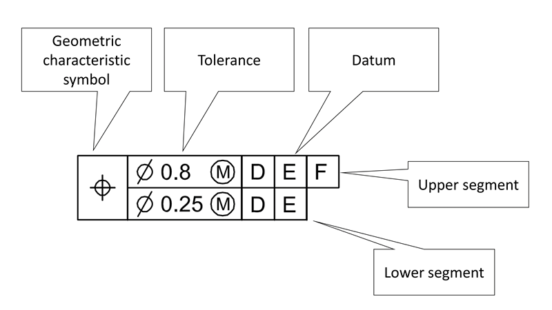
図1. 公差記入枠
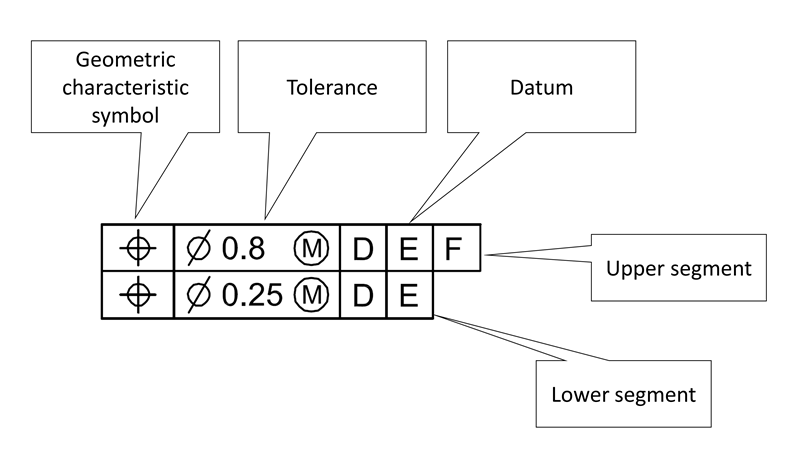
図2. 2つの公差記入枠
1次データムのみを含む複合公差
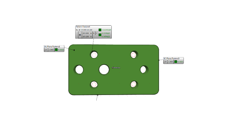
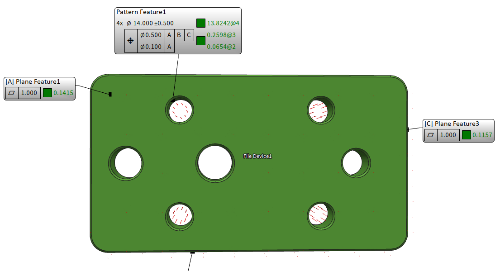
図3. 複合位置度公差で1次データムのみが繰り返される穴のパターン(BuildIT Metrologyソフトウェアで作成)
図3は、BuildIT Metrologyソフトウェアを使用して作成した複合公差です。このソフトウェアに実装されたアルゴリズムは、この記事で説明したASME Y14.5に従って、測定された形状を評価します。
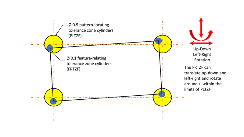
図4. 複合公差によって位置決めされた穴のパターン(1次データムのみ)。この図は、パターンの可能な変位の1つを表している。黄色の円は直径0.5 mm、青色の円は直径0.1 mmの許容範囲を表している
図4は、1次データムのみを含む複合公差の許容範囲とその作用を示しています。
黄色の許容範囲:パターン位置許容範囲規則(PLTZF)。
青色の許容範囲:要素関連位置許容範囲規則(FRTZF)
パターン位置許容範囲規則(PLTZF)はデータムABCに対する位置と姿勢を制約します。
要素関連位置許容範囲規則(FRTZF):
- パターンにある個々の穴の位置と姿勢を制約
- データムAに対する姿勢のみを制約
穴の軸は、パターン位置許容範囲規則(PLTZF)と要素関連位置許容範囲規則(FRTZF)の両方の円筒公差内になければなりません。
図5. 複合公差によって位置決めされた穴のパターンを示すアニメーション(1次データムのみ)。このアニメーションのどの変位も、1次データムのみを持つ複合公差において可能な構成を表しています。黄色と青色の円は、それぞれ直径0.5 mmと0.1 mmの許容範囲を表していることに注意してください。
図5のアニメーションでは、黄色の許容範囲が位置許容範囲規則(PLTZF)を、青色の許容範囲が要素関連位置許容範囲規則(FRTZF)を表しています。
繰り返しになりますが、上段と下段の重要な違いは、下段の公差範囲の姿勢がデータムAに対してのみ制約されることです。下段の位置は特定できません。
したがって、青色の許容範囲(FRTZF)は回転のみ(Aに対して垂直でなければなりません)ですが、データムBまたはCに対して平行移動も回転も自由であり、より大きな許容範囲になります。
特定の位置では小さい青色の許容範囲の一部が、大きい黄色の許容範囲を超える場合があることに注意してください。ただし、要素の軸が大きい許容範囲の制限に違反してはならないため、小さい許容範囲のこれらの部分は使用できません(ASME Y14.5-2018、10.5.1.1)。
1次データムと2次データムを持つ複合公差
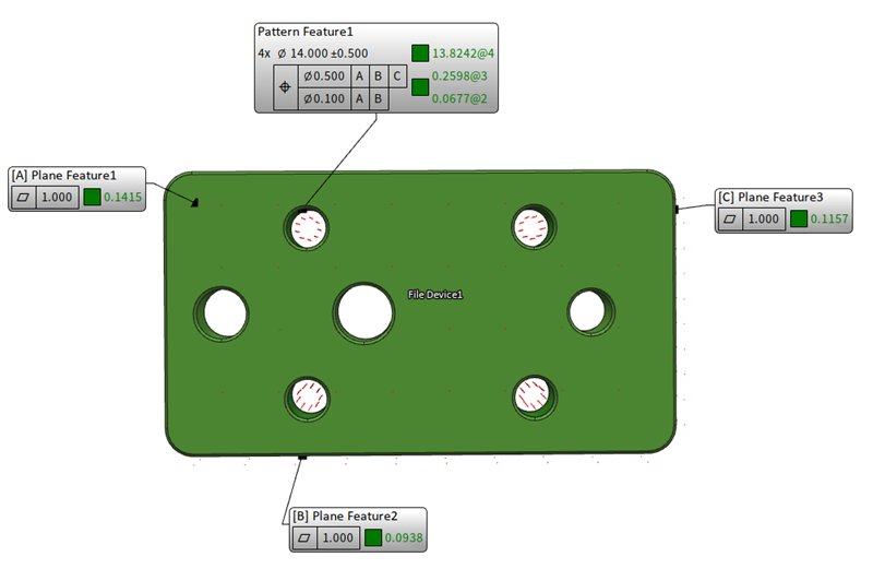
図6. 1次データムと2次データムを含む複合位置度公差の穴のパターン(BuildIT Metrologyソフトウェアを使用して作成)
1次データムと2次データムを含む複合公差では、さらにひとつの自由度が制約されます。図6では、BuildIT Metrologyソフトウェアを使用して作成された、1次データムと2次データムを持つ複合公差の例を示しています。
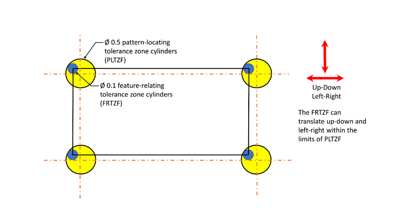
図7. 複合公差によって位置決めされた穴のパターン(1次データムと2次データムあり)。この図は、パターンで発生する可能性のある変位の1つを表わしている。黄色の円と青色の円はそれぞれ直径0.5mmと0.1mmの公差を表していることに注意
図7は、1次データムと2次データムを持つ複合公差の許容範囲とその作用を示しています。
黄色の許容範囲:位置許容範囲規則(PLTZF)。
PLTZFはデータムABCを基準にして位置と姿勢を制限します。
青色の許容範囲:要素関連位置許容範囲規則(FRTZF)
FRTZF
- パターンにある個々の穴の位置と姿勢を制約
- 姿勢をデータムAとデータムBに対してのみ制約
図8. 1次データムと2次データムを持つ複合公差によって位置決めされた穴のパターンを示すアニメーション。このアニメーションの変位はすべて、1次データムと2次データムを持つ場合の複合公差の可能な構成を表示
上段と下段の重要な違いは、下段では、公差範囲がデータムAとデータムBに対して姿勢でのみ制約されることです。下段は、データムAとデータムBに対して位置決めされません。したがって、FRTZFは上下左右に移動できます(図8)。
2つの位置度公差
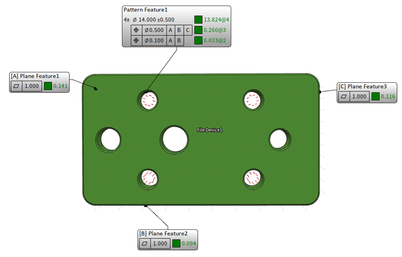
図9. 2つの位置度公差(BuildIT Metrologyソフトウェアを使用して作成)
2つの位置度公差は複合公差ではありません。この例を図9に示します。上段と下段はそれぞれ、データム参照フレームを基準にして定義された位置と姿勢を制限します。
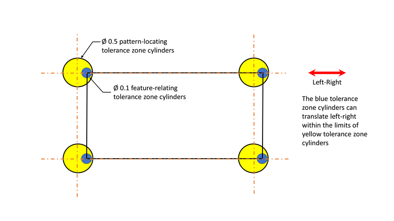
図10. 2つの位置度公差によって位置決めされた穴のパターン
図10は、2つの位置度公差の許容範囲とその作用を示しています。
黄色の許容範囲:上段の位置度公差を表します。
上段の位置度公差はデータムABCを基準にして位置と姿勢を制限します。
青色の許容範囲:下段の位置度公差を表します。
下段の位置度公差はデータムAとデータムBを基準にして位置と姿勢を制限します。
図10に示すように、青色の許容範囲はデータムBによっても位置決めされるようになりました(姿勢のみに制限されていた複合公差とは対照的)。これらは、データムCが許す範囲で左右にのみ自由に移動できます。
図11. 2つの位置度公差によって位置決めされた穴のパターンを示すアニメーション
図11のアニメーションに示すように、今度は下段の位置度公差が姿勢に加えて位置も制限します。したがって、青色の許容範囲も上下移動が制限されています(データムBによる位置の制約)。データムCの位置は制限されていないため、左右にのみ移動できます。
まとめ
複合位置度公差は、穴のパターンを持つ部品の必要な姿勢を指示するための高度な手法です。複雑な部品の位置と姿勢の条件を指示することができます。
上段の位置度公差は位置と姿勢の両方を指定して移動と回転の制約を確立しますが、下段は姿勢のみを指定して回転の制約のみを確立します。下段の位置度公差は上段の位置度公差よりも姿勢の許容範囲が狭いため、回転を微調整できます。
参考文献:
1. ASME Y 14.5-2018, Dimensioning and Tolerancing. New York: American Society of Mechanical Engineers.